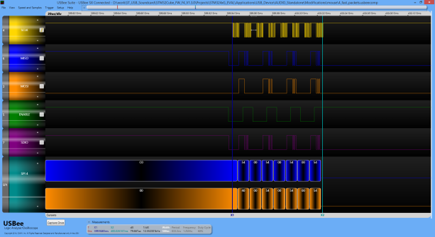
I hooked up my mouse to the Discovery board. I cut the wires from the Nordic chip to the PAW3205 chip. I soldered my wires to PAW3205 and connected them to SPI1 on the Discovery board.
PAW3205DB chip uses a 2-wire half-dupex SPI. Which is not a thing that I dreamed of 🙂 Fortunatelly STM32 F4 series microcontrollers are supporting half-duplex SPI by default by hardware. My first attempt was to use this feature. Unfortunetelly, I could not made it work. I made this half-duplex SPI thing with bit banging GPIO pins just to test if I can communicate at least. It worked, so maybe my clock and the sensor clock was not in synch while using hardware SPI. Maybe re-synch condition was not perfect. But I came to this conclusion just after I did the folowing modifications.
Using full-duplex SPI interface:
Next I decided to use the STM32 with the regular full duplex SPI and a little tweak to connect it to the sensor chip. This way my code and method is at least compatible with every regular SPI interface.
I connected the MISO pin to the sensor SDIO. So receiving is simply solved. Than I connected the MOSI pin to the same line with a 3-state buffer which has an enable pin. I can disconnect it in that way before receiving, and that drives the line into the desired hi-z state.
The trick with the re-sych clock signal is, that it should be kept high before the first valid clock cycle at least for 320ms regarding the datasheet. This is because the chip can go to Sleep2 mode with the default settings. (I disabled sleep and power-down modes in my application, so it could be only 1.7us during normal operation) I had to experiment with this re-sync pulse, but finally it works.
I am using 1,2MHz clock because I don’t want to waste time in my 1ms periods (my planned polling rate and also USB audio and MIDI timing) with slow communication. It seems to be working all right. The distance between the chip and the Discovery board is 7-8 cm with simple ribbon cable while I’m testing.
I can make a motion query in 80us which is pretty good. The original firmware needs 450us with 166KHz clock.
SPI extension
I need a method to extend this SPI line between STM32 and PAW3205, because the sensor should be above the vinyl far from the central Discovery board. I don’t want to build the processor into the vinyl reading units. And on top of that I have to connect 2 reader units to my board later for 2 turntables. I think MAX481 or a similar RS485 extender will do the job. It makes symmetrical signal, and I can extend SCLK, SDIO, WR, 5V, GND and maybe MOTSWK with a CAT6/SFTP Ethernet cable for meters.
I made my simple driver library for PAW3205 chip, and figured out my startup sequence, which disables sleep modes, but keeps all default settings otherwise.


Hi,
I am using this mouse sensor for a project. Could you send more details about the code for communcation? Like, how did you access the registers data?
Thank you.
LikeLike
Hi! The details of the communication is described in the previous blog post. Please read it, it contains all the relevant info for accessing a register.
LikeLike
Thank you.
One more question: How did you set this 320ms delay?
LikeLike
I don’t really remember. I think it is I have a hardware timer for the time base combined with a software counter.
LikeLike
Hi,
I have a little problem. I am able to get right data from 0x06 register (default data – datasheet). But i can’t get the right data from deltaX and deltaY register, i receive only 0 or 255. Could you give me a hand?
LikeLike
How often do you read? Try lower the dpi settings, maybe you wait too much between the reads. Or is it the situation when the mouse does not move?
LikeLike
I make 10 samples/s (100ms period).
When i move the mouse, i get 255 from the register. When it isn’t moving i get 0.
It’s very strange.
Thank you.
LikeLike
My setup is 1600dpi. It means the register reaches 255 after about 4 milimeters of move. So if you move faster than 4mm/sampling time, it will overflow. But there is a register, where you can check the overflow bit.
LikeLike
Need help with PAW3205DB and arduino using your code
LikeLike